Build a 2log Dot
The 2log Dot is a smart RFID reader that can read almost all common RFID cards. Its main purpose is to allow users to authenticate themselves with their smart cards in the system. For example, to log on to a machine.
The 2log Dot is based on the ESP32 and the PN532, two components that are used very often in the maker scene and are easy to obtain. Thanks to the modular design and the exposed GPIO pins, the 2log Dot can be extended at will.
The PCB
The 2log Dot board is a joint project which was developed together with the Technik Kultur Saar e.V. - Many thanks to Matthew for this contribution! In this repository you will find Gerber files for the 2log Dot board.
Order the PCB
- Go to https://jlcpcb.com
- Click on “Instant Quote”
- Click on “Add gerber file” and upload the .zip file you can get from here .
- Do a few necessary changes (let the other settings as it is):
- Choose the number of pieces (Quantity)
- Choose your favorite PCB Color - We prefer black ;)
- Select the appropriate Layers:
- L1: 2logDot-F_Cu.gbr
- L2: 2logDot-In1_Cu.gbr
- L2: 2logDot-In2_Cu.gbr
- L2: 2logDot-B_Cu.gbr
- Proceed with the checkout and complete the order.
Congratulations - in a few days you will have your 2log Dot boards in your hands!
Get the Parts
The PCB consists of a 4-Layer stack. All required parts are through hole components with the exception of the capacitor C1 which is a combined footprint. Besides the PCB itself you need the following parts:
- 24 Led WS2812B Ring with 4 contacts (diameter 66mm)
- SMD Capacitor 5mm diameter, about 10uF
- (alternative) THT Capacitor, about 10uF
- Wemos D1 mini ESP32 (ESP8266 will not work)
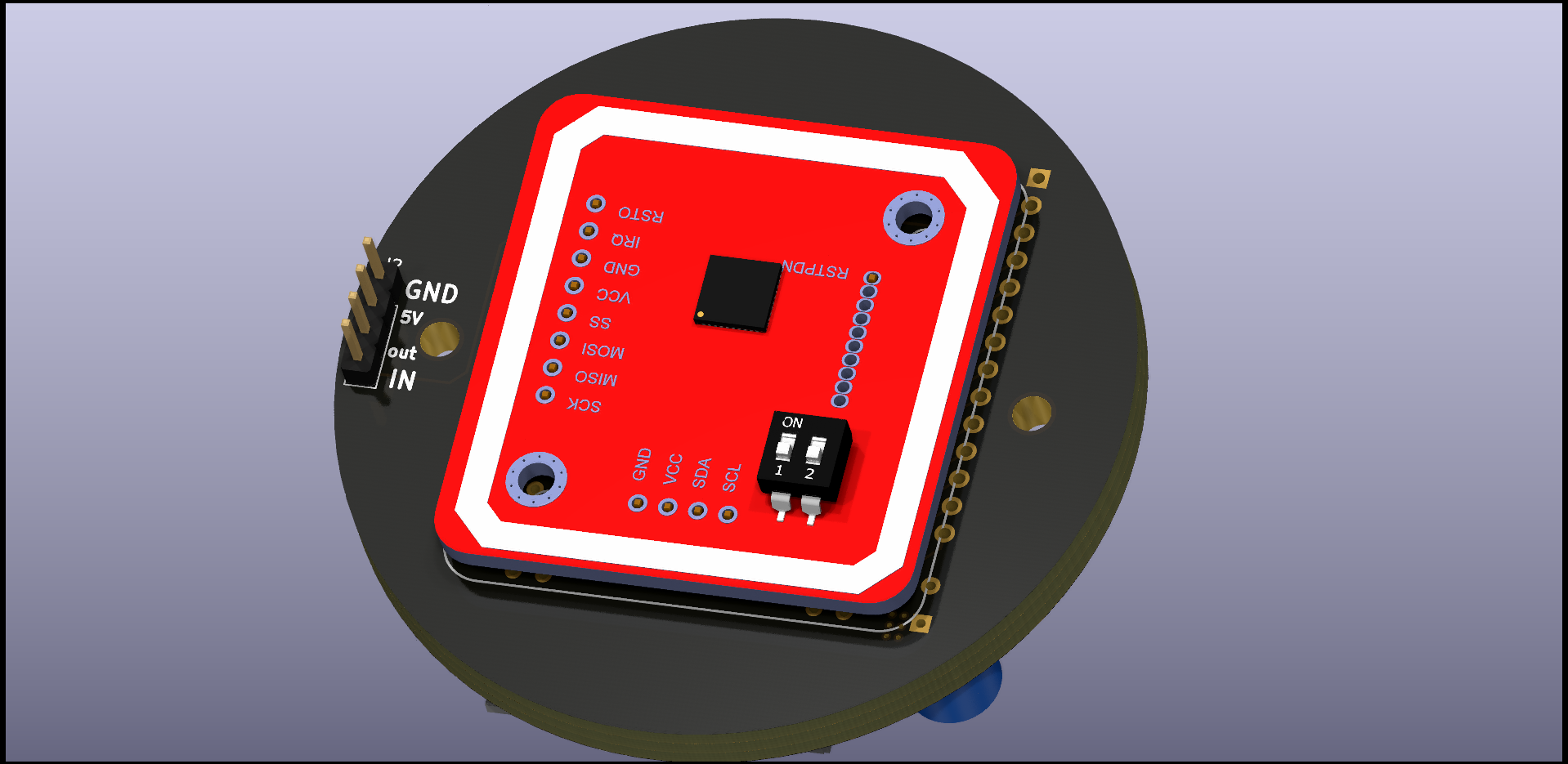
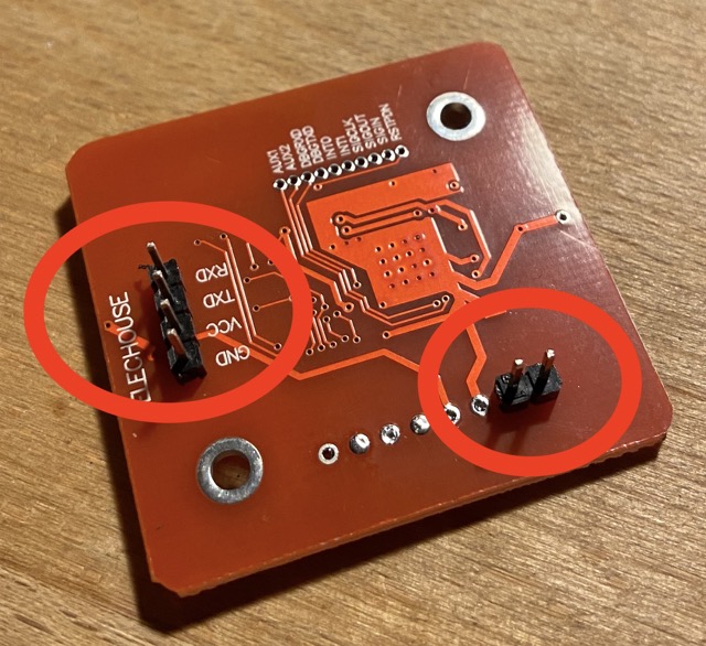
- PN532 RFID Reader V3 (red modules, sold under elechouse brand or clones)
- mini pushbutton (the tiny black/silver ones)
- (optional) 14 Pin Male and 13 Pin Female 2.54mm Pin Header/Socket for expansion port
Renderings
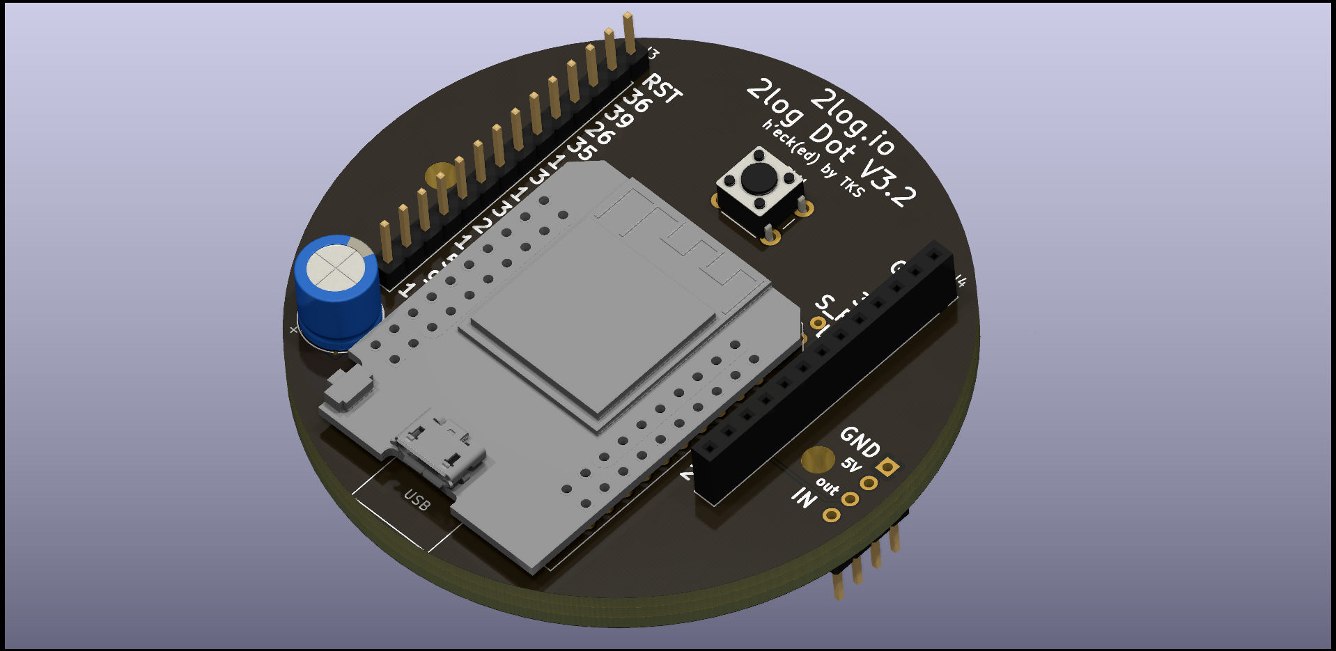
Assembling
To build a Dot you need a soldering iron with a fine tip, solder and some stranded wire.
Attention!
When soldering the dot together, we must pay strict attention to the sequence in which we solder the individual components to the board. If you make a mistake here, you will quickly get into a dead-lock.I highly recommend using the template that can be clamped between the reader and PCB. This ensures that the LED sits above the PN532. This avoids ugly shadows. you can find the stl file here: https://gitlab.com/2log-io/hardware/2log-dot-case
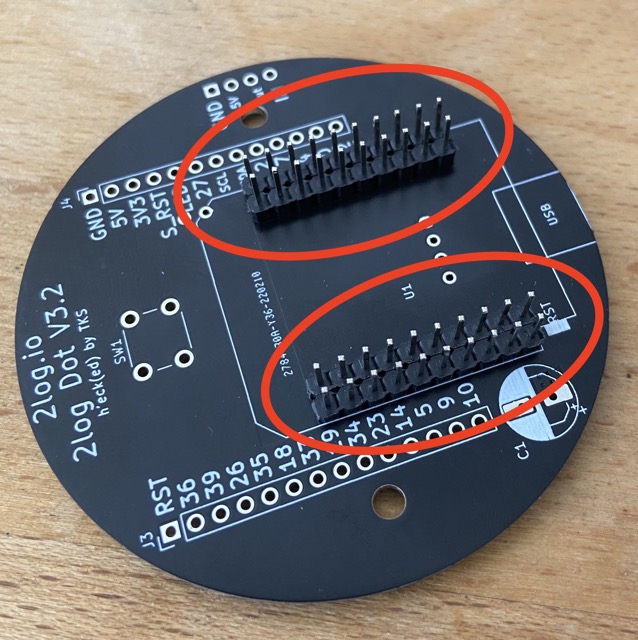
It’s a good idea to put the ESP loose on the pins first, while soldering the pins tight to the board. This ensures that the ESP can be plugged in later without any problems when it is time for its turn.
gi
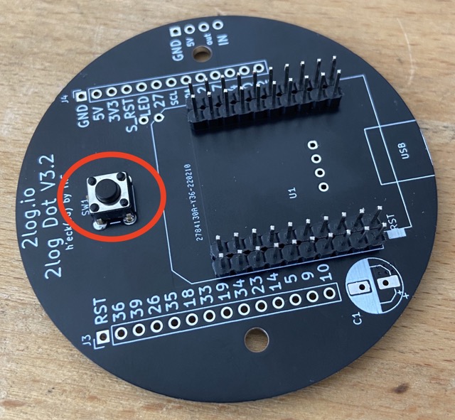
Next, the button can be soldered on.
Solder the pins to the PN532. Also here it makes sense to insert the pins loosely into the board during soldering. Otherwise it can happen that you solder the pins a little bit crooked. Then they no longer fit into the PCB and you have trouble.
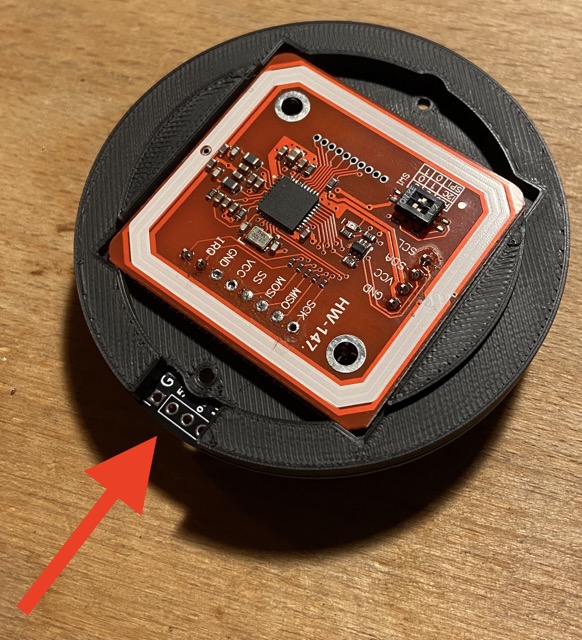
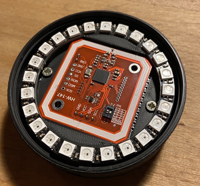
Now you can connect the reader to the board. In between comes the template that we printed out earlier with the 3D printer. Make sure that the recess in the template is positioned so that you have free access to the pins for the LED ring.
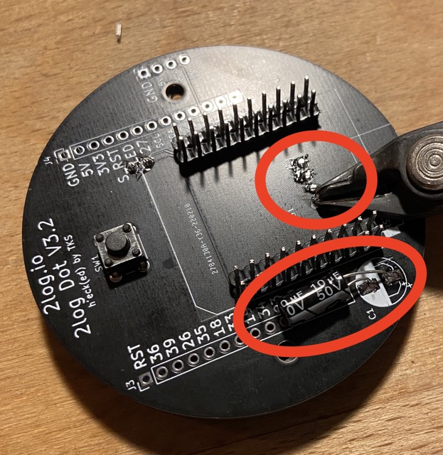
Now we can solder the capacitor and take the opportunity to cut off the protruding pins of the PN532.
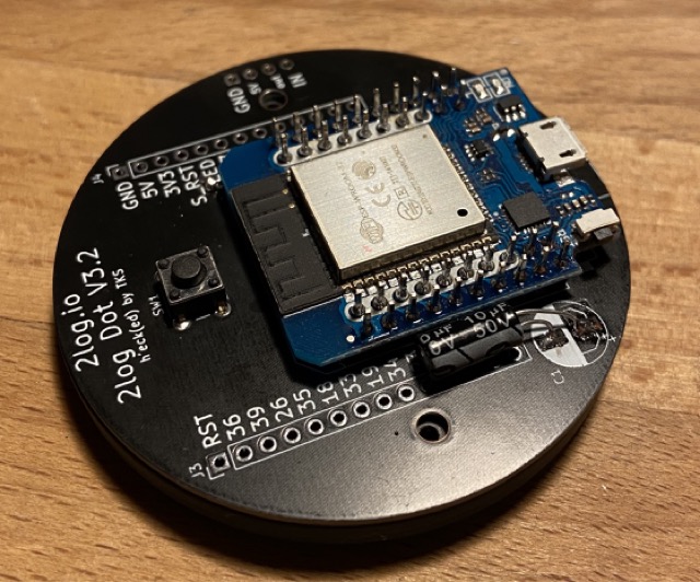
Next, the ESP can be soldered.
Now we can work on the LED ring. For this I took copper wire and stripped it. Next, the stranded wire is tinned and soldered to the contacts of the LED ring.
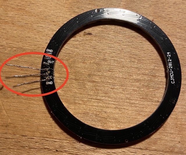
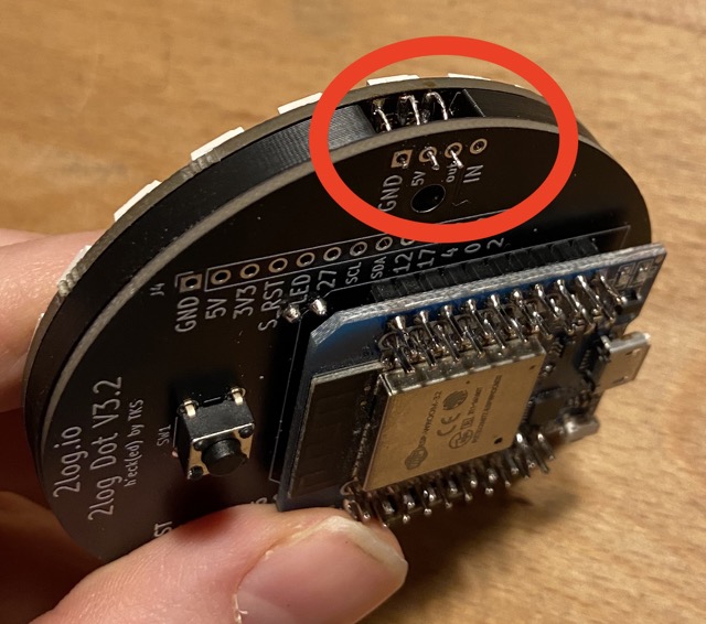
Bend the pins upwards and put the ring on the template. Here you have to thread the stranded wire through the holes of the board and solder it from the backside.
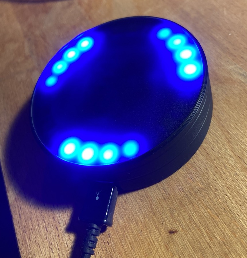
Congratulations! You now have a 2log Dot.
The case
The case can be printed with normal PLA. Get the stl files from here. I particularly like the matte look of the Extrudr NX2 black matte. For the lid, simply laser a circle with a diameter of 70.5 mm. The material used for this is BLACK & WHITE 9H04 SC.
Flash the Firmware
- Make sure that the drivers for the serial adapter of your ESP32 and the Python tool “esptool.py” is installed.
- Then download the latest firmware build from our CI Toolchain here: https://gitlab.com/2log-io/2log-dot/-/jobs/artifacts/main/download?job=build
- Connect the dot with a micro usb cable to your PC and flash the binaries with the following command to your ESP:
esptool.py  \
            -b 460800 \
            --before=default_reset \
            --after=hard_reset write_flash \
            --flash_mode dio \
            --flash_freq 40m \
            --flash_size 4MB \
            0x1000 bootloader/bootloader.bin \
            0x10000 2log-Dot.bin \
            0x8000 partition_table/partition-table.bin \
            0xe000 ota_data_initial.bin
You may need to add -p /dev/<serial-adapter> with the path to the serial adapter in case the system can’t detect the serial adapter automatically.
Connect the Dot with your 2log instance
You can set up the devices either with the 2log app or manually with a Linux Shell. Using the app is straight forward and will be explained in the corresponding chapters.
Provisioning without mobile app
Here we explain how to provision a Dot via a direct SSH connection. You only need a command line for the manual setup.
You can also use this protocol to create your own program code for provisioning.
-
Press the button on the back of the Dot with a pointed object for several seconds. Once the Dot is in pairing mode, it will start glowing purple and open a WiFi hotspot.
-
Connect your laptop to the WiFi with the SSID
I'm a Dot. -
Enter the following command into your linux console:
openssl s_client -connect 192.168.4.1:8443
After a few console outputs, a connection to the Switch should be established.
- Send the following JSON command to the device by typing it into the console and confirming with return:
{"cmd": "hi"}
The device will respond with something similar to
{
	"cmd":	"welcome",
	"device":	{
		"sid":	"I5O2",
		"uuid":	"3C:61:05:DE:8A:A4"
	}
}
Write down the short id (sid) somewhere. You will need it later to assign the device. In the example here the device has the sid I502
- Now we can send the configuration to the device with the following JSON command
{
   "cmd":"setconfig",
   "ssid":"<YOUR_SSID>",
   "pass":"<YOUR_PASSWORD>",
   "extconfig":{
      "server":"<YOUR_2LOG_SERVER>",
      "testconfig":false
   }
}
- The device will respond with
{ "cmd":"setconfig","status":1}
Which means that the device has received the data.
- The device will now reboot and try to connect to the server. The Dot will stop glowing once it is successfully connected to the 2log instance. Now you can assign a function to the Dot using the four-digit short ID.