The 2log documentation is being created here little by little. The documentation was written with the goal to enable Fablabs and Makerspaces to use and operate the 2log system on their own.
All hardware components were intentionally designed based on through-hole parts to allow less experienced makers to solder the parts together.
Feedback welcome!
If any points are not described in enough detail I am grateful for any feedback. Pull requests are welcome.
1 - Overview
What is 2log?
2log is a free community management system for workshops, fablabs, maker- and hackerspaces.
It is a modular hardware and software solution that digitally links machines, users and processes and makes them remotely trackable. Each device with a power cable - from the laser cutter to the coffee machine - can be connected to your 2log instance with the 2log Switch within a few minutes.
Your advantages:
Protect the machines from unauthorized use thanks to individual usage
authorizations.
Bill machine run time either as a flat rate or by the second based on time of use.
Transfer your existing machinery to 2log. No changes to the machines are necessary - the manufacturer‘s warranty for the equipment is retained.
Reduce your power consumption. Unused machines switch off automatically.
Receive statistics on the use of your machines. With 2log you can monitor the load in real time. You can see at any time who has been working on which machine when and where.
Use the 2log admin app or the web platform to always have a full overview of the processes in your workshop.
Integrate 2log into your existing systems (e.g. CoBot).
Bill products like coffee or snacks with a self service terminal.
Easy authentication via RFID cards or with with the 2log App by scanning QR Codes.
How it works
In order to integrate a machine into 2log, no structural changes need to be made. The 2log switch is simply plugged between the power plug of the machine and the socket. The setup process is so simple that you can easily do it yourself in minutes.
No problem - there are a number of workshops from very different sectors that have been using 2log successfully for several years.
2.1 - Shared joinery workshop in Kleve
A commercial joinery that uses 2log to share the use of its machinery between several independent self-employed carpenters and subcontractors.
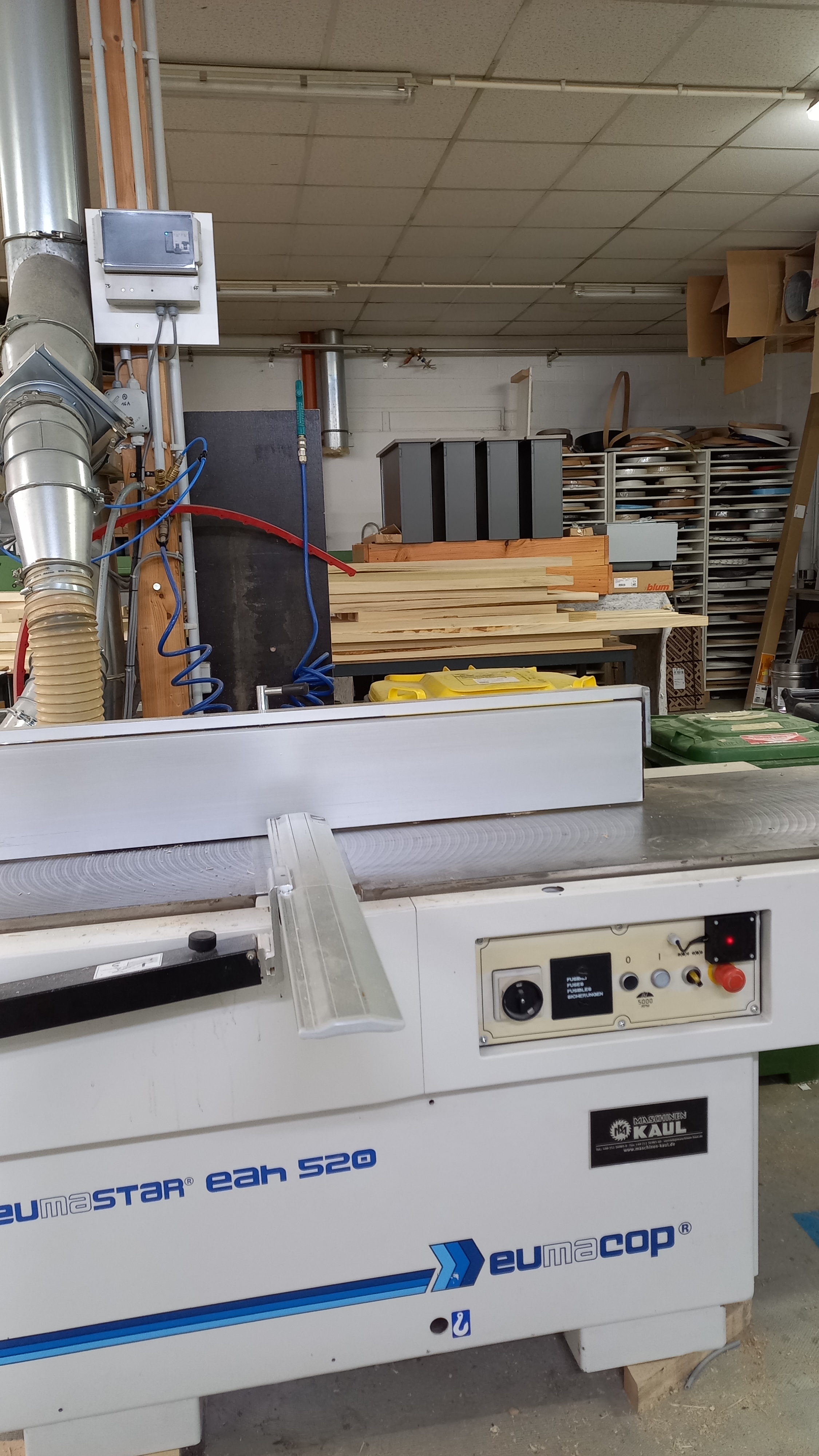
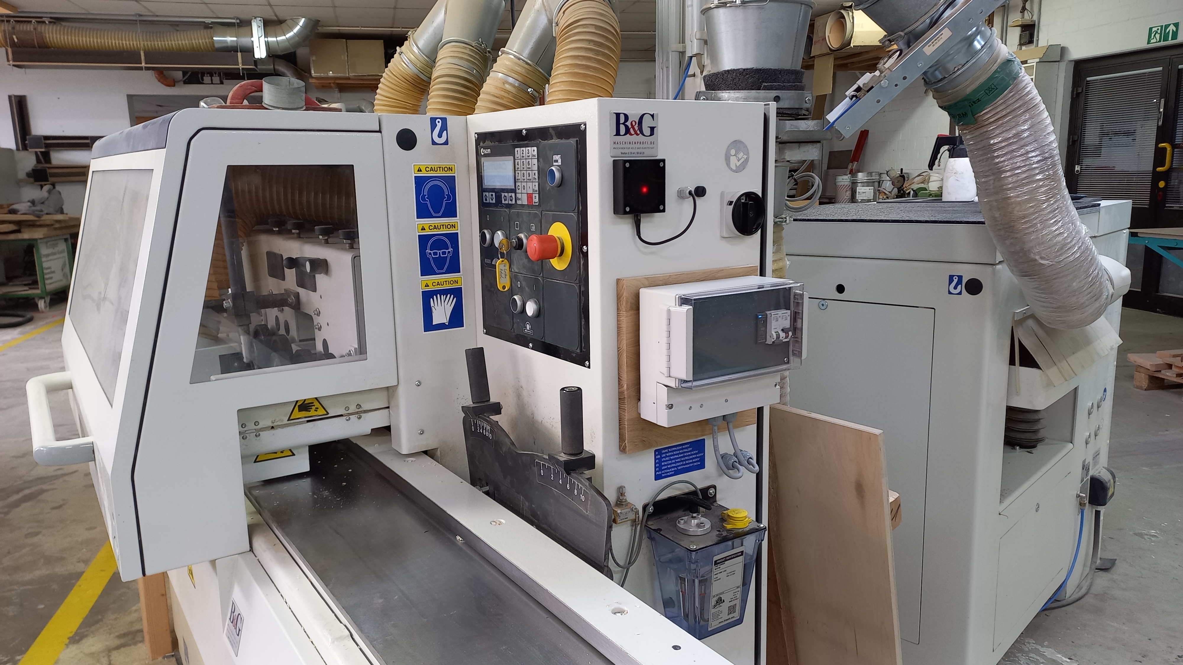
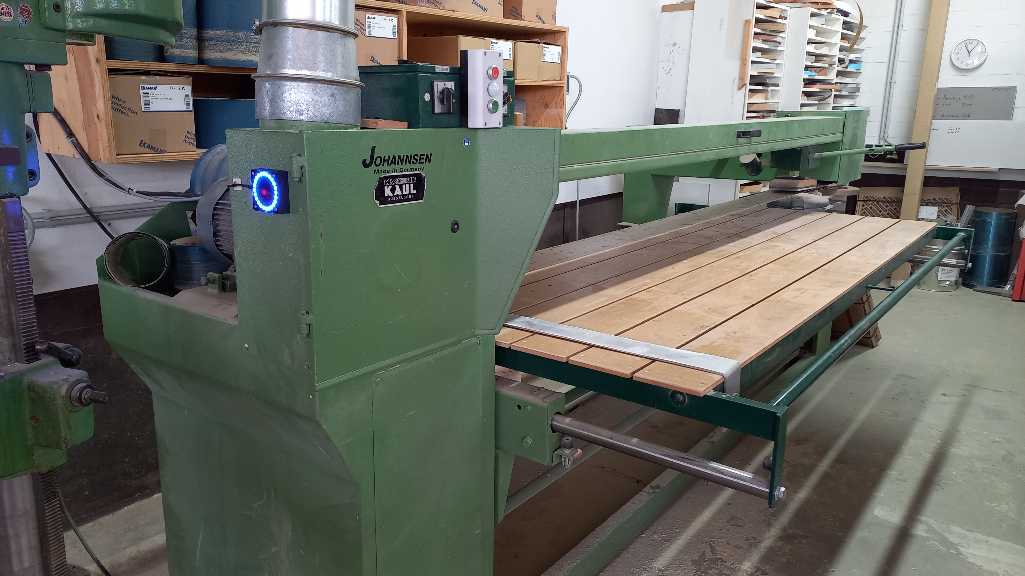
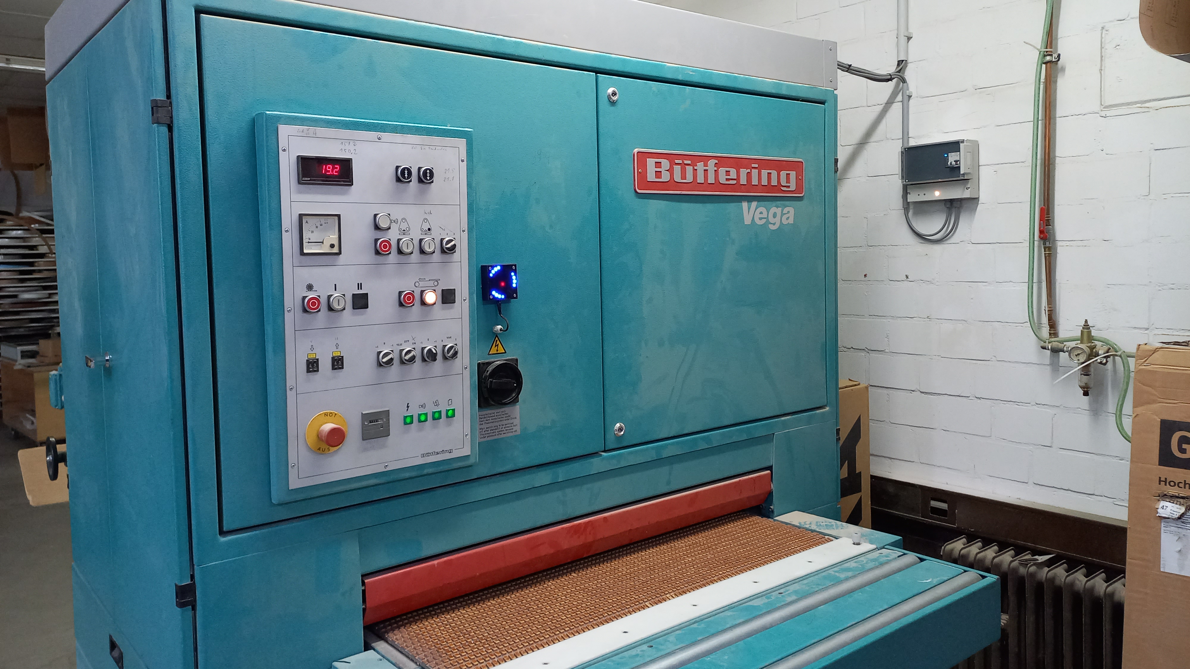
A carpentry workshop in Kleve that built 2log entirely on its own just by using this online documentation. They experimented extensively and found new ways to integrate even very large machines into 2log. In many cases, access control was implemented by interrupting existing safety mechanisms with relays. For example, by interrupting the circuit of sensors that check whether safety flaps are closed.
The operators of this workshop are also part of the community and are present on the Discord channel. They can provide many tips when it comes to integrating large machines.
A few pictures
2.2 - StudioLab - TU Kaiserslautern
The Studiolab is a workshop for architecture students at the RPTU in Kaiserslautern.
The Machines
In total, we operate:
2x band saws
3x circular saws
2x belt sanders
2x styrocuts
2x disc sanders
How we use 2log.io
Overall, more than 200 students have an active account and use the workshop on a regular basis. Because of the logfiles from every machine, we can keep track of the utilization and wear. This helps us to estimate the condition for example of the saw blades.
Extended opening hours
Students can access the workshop 24/7 via 2log to make models for their assignments during their studies. Due to the traceable history of the machines, we have less vandalism in our workshop. Furthermore, the machines are handled more carefully, and the shop floor is left behind cleaner. We don’t need to employ a supervisor with opening hours, because all the access control and authorization of the machines is handled by 2log. With 2log, its possible to work on the weekends or use the machines whenever it suits you. Before implement this login system, the workshop was crowded and the students had to share the machines. With the 24/7 opening times, the working hours are spread over the entire time. This ensures that the workshop is not overcrowded.
Safety instructions
In addition, we automatically check for a valid safety instruction with 2log. Only after a successful safety training and the safety briefing the account will be added to 2log. This is really important for our insurance protection. The option to create the account for a limited time only helps us to keep track of this topic and ensures that no account has an expired instruction.
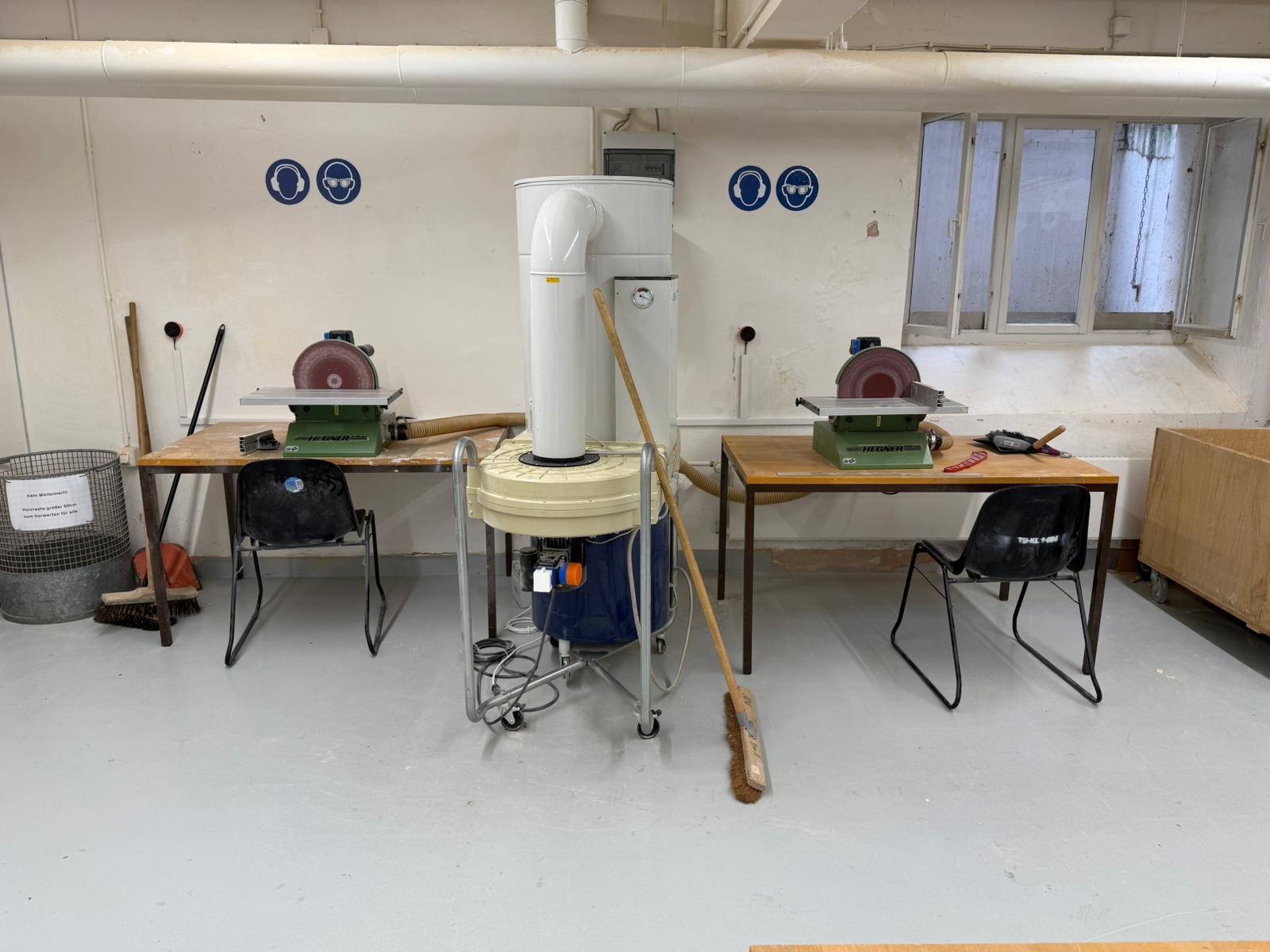
Less dust - better air!
Another key advantage with 2log is the fact that we can check and control the dust extraction of the working machines. If extraction is necessary, the machine will only be unlocked if the corresponding extraction is running. As soon as you try to unlock a machine, the extraction starts automatically via 2log and ends afterwards. Therefor you don’t have to worry about turning on or off the ventilation. Because of this, the whole workshop is less dusty which is also healthier for the people working there.
2log - Easy to set up, easy to maintain
Fortunately, the components for the new dots were soldered and assembled for us by the university’s electronics workshop using the instructions on the 2log website. Thanks to the new software version, we were able to use the existing ShellyOS Shelly Plus Plug S to integrate the switches, which meant that the integration did not require any changes to the purchased hardware. As we have some machines with a high starting current or a three-phase connection, we could not use standard ShellyPlugs for this. As there are no three-phase switches available, we used a Shelly 1PM to switch a three-phase contactor. To avoid the high starting currents, we had to use a different switch. A 2log-switch was realised by using a Shelly Pro EM 50 with energy metering. Both switch variants were easy to implement thanks to the option of using ShellyOS.
To get a better impression, have a look at the attached pictures 😊
Luis and Daniel
Pictures
2.3 -
3 - Getting Started
Here you will learn step by step how to set up your own 2log instance.
Preamble
2log is a free OpenSource project that can be used freely and without charge under the terms of the GPL v.3/ AGPL v.3. This means that the authors of 2log.io do not accept any liability for any damage or infringement of valid rights caused by the use of 2log.io.
Prerequisites
In order to operate 2log, certain technical requirements must be met.
Server and Network
To run your own 2log instance, a Docker-enabled computer with x86-64 architecture is recommended. Since 2log is implemented in a very resource-efficient way, a headless Linux server with a 1.4GHz dual core and 4GB memory is sufficient.
The 2log hardware components communicate with the server via WiFi. Accordingly, the server and the IoT devices must be able to reach each other over a 2.4GHz network.
For the operation of 2log the server must be able to send e-mails. For this purpose, an SMTP mail server is required.
Machines and devices
Since the 2log Switch controls access to the devices by connecting and disconnecting power, it is important to ensure that all connected machines can handle this.
Since 2log detects via power consumption whether the machine is in stand-by mode or actually working, it is ensured that a machine is never switched off from operation.
Depending on the smart sockets used for the 2log switches, it must be ensured that the machines do not draw more current than is supported by the connectors.
3.1 - Setup the 2log.io Server Application
Learn how to set up a 2log instance
The easiest way to set up your 2log instance is to use Docker.
Using Docker
The easiest way to set up your 2log instance is to use the Dockerfile provided in the repository.
First, make sure that Docker is installed with the associated tool docker-compose.
mkdir ~/2log
cd ~/2log
wget https://gitlab.com/2log-io/2log.io/-/raw/main/docker/docker-compose.yaml
docker-compose up
By default, the WebAssembly frontend can be reached via Port 8080. If the server is running on your local machine, just visit http://localhost:8080 in your web browser and the UI should come up. You can now login into your instancy by accessing the WebSocket service which is by default accessible via port 4711. To check your instance is up and just type ws://localhost:4711. The initial default login is “admin” with passwort “password”. Don’t forget to change the password after the first login!
Note:
The frontend does currently not work in mobile browsers. Since the frontend is written in Qt, it can easily be compiled as a native Android *.apk. (Which is much cooler anyway).
Setup Mail Server
The mail server can be configured directly via the environment variables. The easiest way to define these settings is directly in the docker-compose file.
#--------- Mail Server config
#- MAIL_HOST=smtp.mydomain.com
#- MAIL_USER=admin
#- MAIL_PASS=password
#- MAIL_ADDR=2log@mydomain.com //sender eMail address
#- MAIL_CONNECTION_TYPE=TLS // or SSL or TCP
#- MAIL_SENDER=2log.io // readable sender name (optional)
#- MAIL_PORT=587
All operational data of the 2log instance is stored in the folder ./2log.io. It is strongly recommended to back up the folder at regular intervals.
3.2 - Let your community grow!
Learn how to add or import members to your 2log.io instance
To add new members you can either use the web portal or the 2log Admin app.
2log has two separate user administrations. Members and administrators are managed separately and independently. This page is only about adding members.
Add a single member
The easiest way to add a new member is via the app or web portal. The procedure is identical for both variants.
Log in to your 2log instance with your admin account.
Switch to the “User” menu item
Click “New user”
Fill in the form fields.
The alias field is optional. The alias must be unique and can be used by the members besides the email address to log in. If there is already a user with this alias, an error message will be displayed. The alias can also be used to call the user by his nickname.
The eMail address is mandatory and must be unique. If there is already a user with this email address, an error message will be displayed.
Currently there are three different roles: “Member”, “employee” and “guest”. Unlike “employee”, “guest” is not yet used productively. The role Employee is relevant for the machine time accounting where there is the option “Free for employees”.
In the “Account balance” box, a starting balance can be set and an RFID card can be added.
If you use the app on an RFID-enabled smartphone, you can scan the new card directly with your phone.
Alternatively, the use of an “Admin Dot” is possible. This can be set up in the “Administration” area and allows convenient reading of cards from the web app.
Grant access rights to individual machines or groups
Click on “Create user”.
Congratulations! This is your first community member.
Add members with the CSV importer
If many users are created at once, for example when the new class starts the semester, the CSV Importer is the better choice.
Log in to your 2log instance with your admin account.
Switch to the “User” menu item
Click “CSV Import”
Download the sample template to see an example of a valid import file.
The importer uses the labeling of the header, i.e. the first line, to assign the individual fields. Accordingly, it does not cause any problems if additional fields or a different order is used.
Upload your CSV File. You will now see a preview of the records found.
If no role has been assigned yet, you can assign one using the button in the header of the preview. The same applies to the group. It is possible to add a group permission to a record uploaded via CSV.
Confirm the import with a click on “start import”.
Note:
If a user with the specified email address or card ID already exists, the user is not created but edited accordingly. For example, the credit specified in the CSV is added to the existing account balance or a new email address is assigned.
3.3 -
4 - Build the Hardware Components
Here you will learn how to build the 2log hardware components.
Disclaimer
Software, schematics and building instructions were made to the best of our knowledge. We provide them here free of charge because we think it could be of use.
However, we don’t take any responsibility nor liability for using this software nor for the installation or any tips, advice, videos, etc. given by any member of this site or any related site.
4.1 - Build a 2log Dot
Learn how to build a 2log Dot
The 2log Dot is a smart RFID reader that can read almost all common RFID cards. Its main purpose is to allow users to authenticate themselves with their smart cards in the system. For example, to log on to a machine.
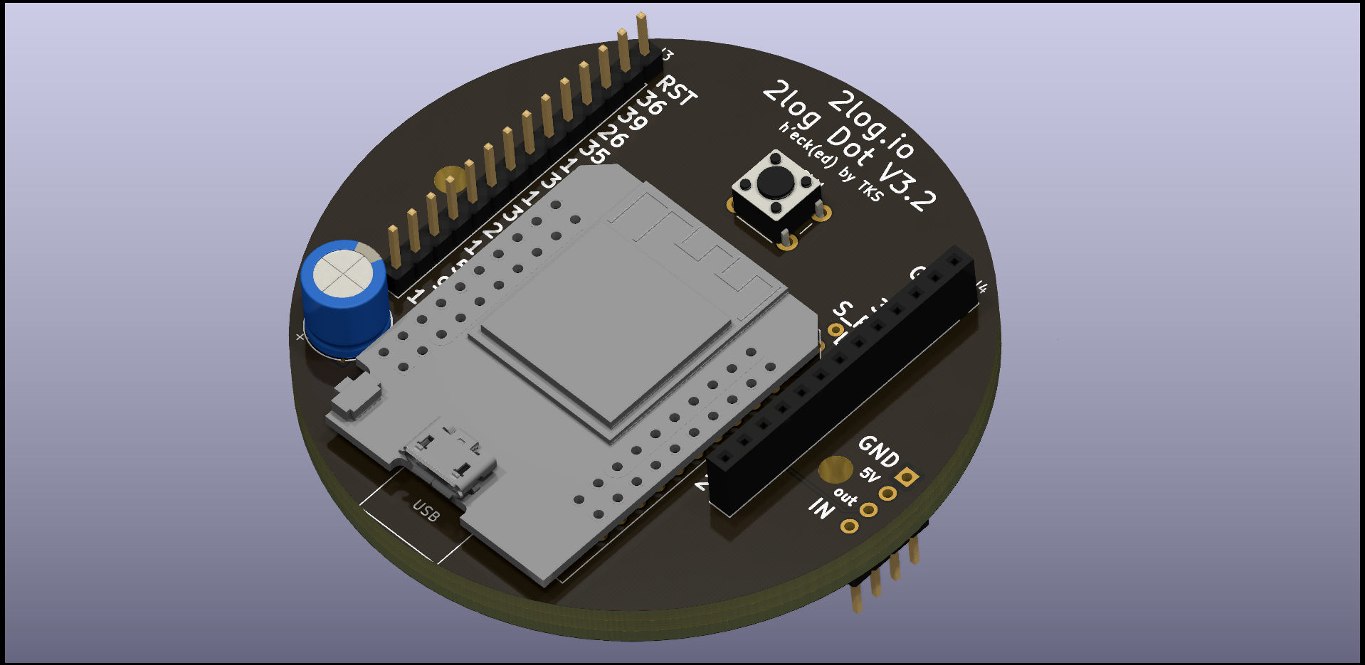
The 2log Dot is based on the ESP32 and the PN532, two components that are used very often in the maker scene and are easy to obtain. Thanks to the modular design and the exposed GPIO pins, the 2log Dot can be extended at will.
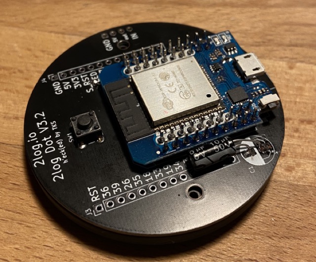
The PCB
The 2log Dot board is a joint project which was developed together with the Technik Kultur Saar e.V. - Many thanks to Matthew for this contribution!
In this repository you will find Gerber files for the 2log Dot board.
Click on “Add gerber file” and upload the .zip file you can get from here .
Do a few necessary changes (let the other settings as it is):
Choose the number of pieces (Quantity)
Choose your favorite PCB Color - We prefer black ;)
Select the appropriate Layers:
L1: 2logDot-F_Cu.gbr
L2: 2logDot-In1_Cu.gbr
L2: 2logDot-In2_Cu.gbr
L2: 2logDot-B_Cu.gbr
Proceed with the checkout and complete the order.
Congratulations - in a few days you will have your 2log Dot boards in your hands!
Get the Parts
The PCB consists of a 4-Layer stack. All required parts are through hole components with the exception of the capacitor C1 which is a combined footprint.
Besides the PCB itself you need the following parts:
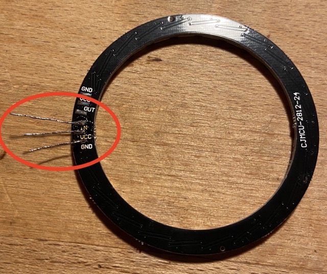
24 Led WS2812B Ring with 4 contacts (diameter 66mm)
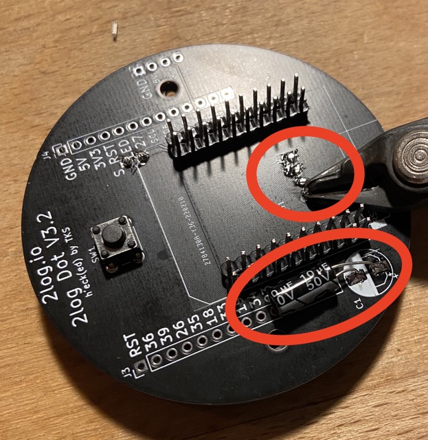
SMD Capacitor 5mm diameter, about 10uF
(alternative) THT Capacitor, about 10uF
Wemos D1 mini ESP32 (ESP8266 will not work)
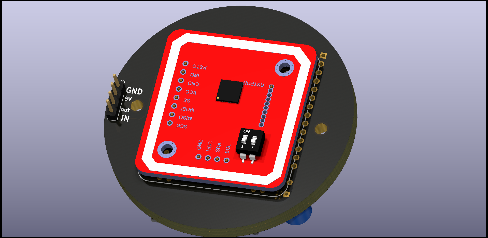
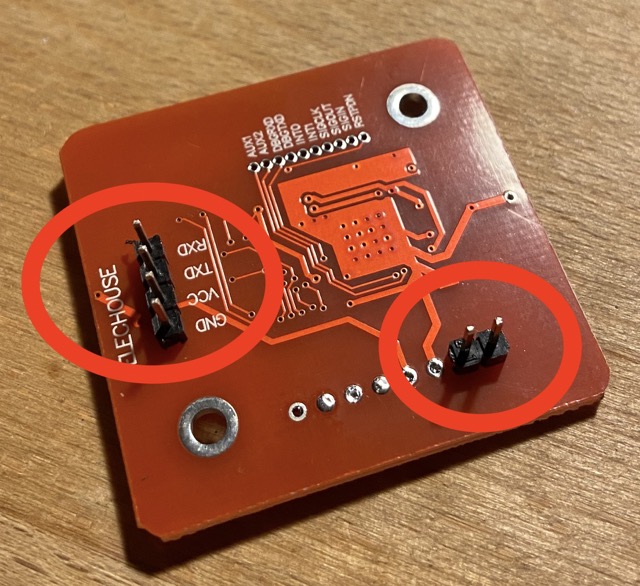
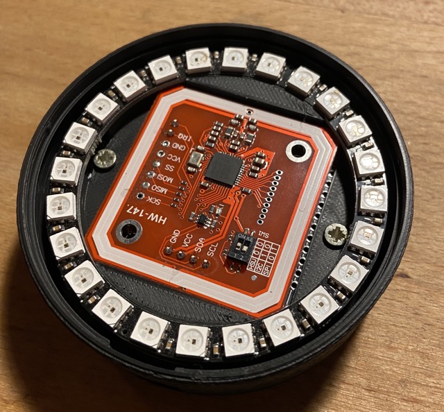
PN532 RFID Reader V3 (red modules, sold under elechouse brand or clones)
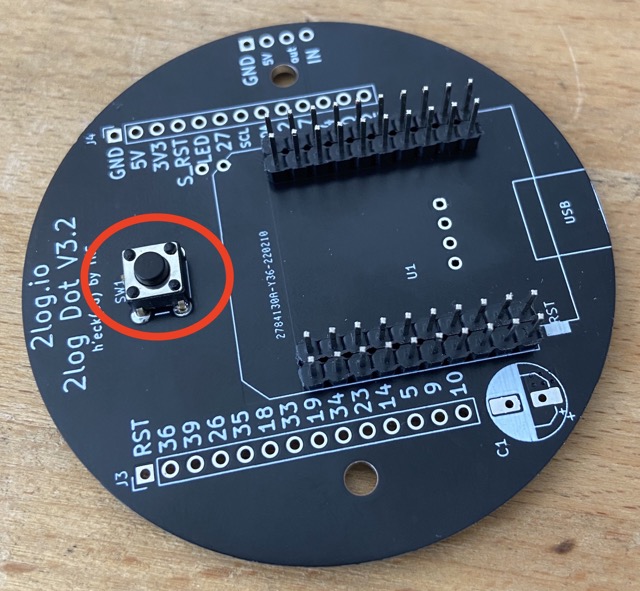
mini pushbutton (the tiny black/silver ones)
(optional) 14 Pin Male and 13 Pin Female 2.54mm Pin Header/Socket for expansion port
Renderings
Assembling
To build a Dot you need a soldering iron with a fine tip, solder and some stranded wire.
Attention!
When soldering the dot together, we must pay strict attention to the sequence in which we solder the individual components to the board. If you make a mistake here, you will quickly get into a dead-lock.
I highly recommend using the template that can be clamped between the reader and PCB. This ensures that the LED sits above the PN532. This avoids ugly shadows. you can find the stl file here: https://gitlab.com/2log-io/hardware/2log-dot-case
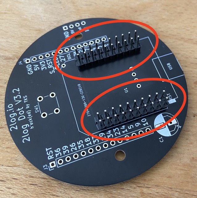
It’s a good idea to put the ESP loose on the pins first, while soldering the pins tight to the board. This ensures that the ESP can be plugged in later without any problems when it is time for its turn.
gi
Next, the button can be soldered on.
Solder the pins to the PN532. Also here it makes sense to insert the pins loosely into the board during soldering. Otherwise it can happen that you solder the pins a little bit crooked. Then they no longer fit into the PCB and you have trouble.
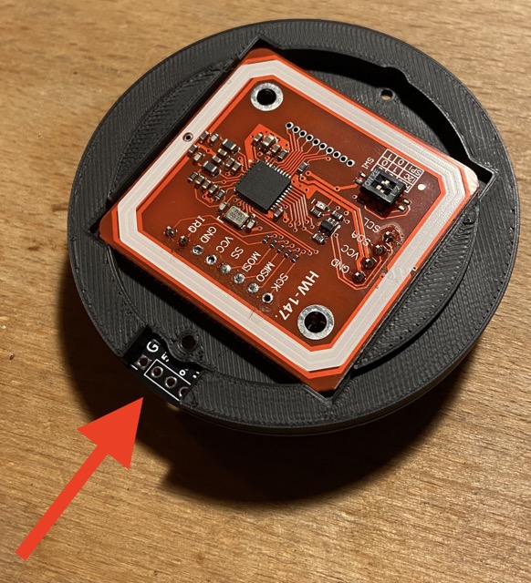
Now you can connect the reader to the board. In between comes the template that we printed out earlier with the 3D printer. Make sure that the recess in the template is positioned so that you have free access to the pins for the LED ring.
Now we can solder the capacitor and take the opportunity to cut off the protruding pins of the PN532.
Next, the ESP can be soldered.
Now we can work on the LED ring. For this I took copper wire and stripped it. Next, the stranded wire is tinned and soldered to the contacts of the LED ring.
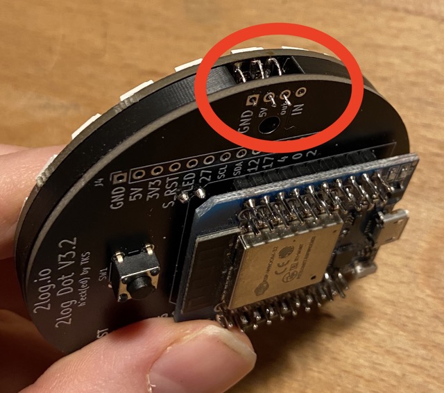
Bend the pins upwards and put the ring on the template. Here you have to thread the stranded wire through the holes of the board and solder it from the backside.
Congratulations! You now have a 2log Dot.
The case
The case can be printed with normal PLA. Get the stl files from here. I particularly like the matte look of the Extrudr NX2 black matte. For the lid, simply laser a circle with a diameter of 70.5 mm. The material used for this is BLACK & WHITE 9H04 SC.
Flash the Firmware
Make sure that the drivers for the serial adapter of your ESP32 and the Python tool “esptool.py” is installed.
You may need to add -p /dev/<serial-adapter> with the path to the serial adapter in case the system can’t detect the serial adapter automatically.
Connect the Dot with your 2log instance
You can set up the devices either with the 2log app or manually with a Linux Shell. Using the app is straight forward and will be explained in the corresponding chapters.
Provisioning without mobile app
Here we explain how to provision a Dot via a direct SSH connection. You only need a command line for the manual setup.
You can also use this protocol to create your own program code for provisioning.
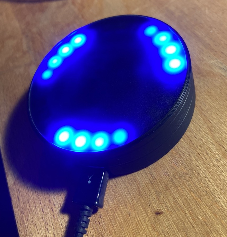
Press the button on the back of the Dot with a pointed object for several seconds. Once the Dot is in pairing mode, it will start glowing purple and open a WiFi hotspot.
Connect your laptop to the WiFi with the SSID I'm a Dot.
Enter the following command into your linux console:
openssl s_client -connect 192.168.4.1:8443
After a few console outputs, a connection to the Switch should be established.
Send the following JSON command to the device by typing it into the console and confirming with return:
Which means that the device has received the data.
The device will now reboot and try to connect to the server. The Dot will stop glowing once it is successfully connected to the 2log instance.
Now you can assign a function to the Dot using the four-digit short ID.
4.2 - Build a 2log Switch
Learn how to build a 2log Switch
The 2log Switch is a smart wireless socket that can switch power and measure energy consumption. It communicates via WiFi with the 2log server and ensures that only authorized users can use the machines. By measuring the power consumption, the system knows exactly how long the machine has been in use.
Shelly Plus Plug S and Shelly PLus 1 PM (recommended)
The new generation of Shelly devices comes with Shelly OS, which is fortunately very open and comes with well-documented APIs. In addition, the Shelly smart meters already support outgoing websocket connections out of the box, making them perfect for use with 2log.
Before you start, make sure that your 2log instance is up to date.
The endpoint for Shelly sockets waits on port 4712 for incoming websocket connections. If you are using Docker, make sure that docker-compose.yaml is configured accordingly.
Log in to the web portal of the Shelly device and carry out a firmware update.
Connect the Shelly socket to the Wifi network via which the 2log server is accessible.
Configure an “outbound websocket” connection. Enter the IP address of the 2log server. Do not forget to enter the port 4712. The address then looks something like this: ws://<2log IP>:4712.
Log in to the 2log admin interface, go to the device explorer in the settings area.
The switch should appear here in the “Unregistered Devices” area. Make a note of the short ID. You will need it later to assign the switch to a machine.
Go to the settings of your 2log resource. Click on “Set up now” for the switch. You can answer the question as to whether the device is already connected to the network with “Yes”. Now use the short ID to assign the new Shelly to the machine.
Now configure the switch via the web interface so that it is not publicly accessible. For example, by assigning a password and deactivating the public access point if necessary.
Shelly Plug S and Shelly 1PM (deprecated)
To use an Shelly Plug S or a Shelly 1 PM (the older models, not the PLUS version!) as a 2log switch, the 2log firmware must be flashed manually. This process is a little fiddly, not entirely trivial and fortunately no longer necessary thanks to the new generation of Shelly devices. However, if you have this hardware available and are not afraid of the effort, you can get started right away. The only thing you need is an FTDI / Serial Programmer and possibly a soldering iron with a fine tip.
Danger!
If your device connects to mains electricity (AC power) there is danger of electrocution if not installed properly. If you don’t know how to install it, please call an electrician (Beware: certain countries prohibit installation without a licensed electrician present). Remember: SAFETY FIRST. It is not worth the risk to yourself, your family and your home if you don’t know exactly what you are doing. Never tinker or try to flash a device using the serial programming interface while it is connected to MAINS ELECTRICITY (AC power).
Flashing the Firmware
Officially supported are currently the models “Shelly Plug S” and “Shelly 1PM”. Regarding the 1PM, you have to be careful not to accidentally buy the plus version with the square case. We need the version with the ESP8266 and the round case.
To flash a Shelly Plug S socket you have to do the following steps:
Download the firmware binaries from our CI Pipeline
You can set up the devices either with the 2log app or manually with a Linux Shell. Using the app is straight forward and will be explained in the corresponding chapters.
Provisioning without mobile app
Here we explain how to provision a Switch via a direct SSH connection. You only need a command line for the manual setup.
You can also use this protocol to create your own program code for provisioning.
Press the button of the Switch for several seconds. Once the Dot is in pairing mode, it will start blinking slowly and open a WiFi hotspot.
Connect your laptop to the WiFi with the SSID I'm a Switch.
Enter the following command into your linux console:
openssl s_client -connect 192.168.4.1:8443
After a few console outputs, a connection to the Switch should be established.
Send the following JSON command to the device by typing it into the console and confirming with return:
Which means that the device has received the data.
The device will now reboot and try to connect to the server. The Switch will stop blinking and glow continuously once it is successfully connected to the 2log instance. Now you can assign a function to the Dot using the four-digit short ID.
5 - Machine Control
Here you will learn how to integrate a machine into 2log.io
One of the main functions of 2log is the access control of machines. A machine can be any device with a power cable. From the laser cutter to the band saw to the 3D printer, pretty much any device can be integrated.Thanks to 2log rights management, each user can be given permission to use specific machines. This is done either via individual permissions or via groups.
Via the power consumption, 2log can determine whether a machine is actually working or only in stand-by mode. In this way, the machine usage can be charged according to different pricing models.
Prerequisities
Certain hardware and software components are required to set up a machine access control.
The machine itself
Since the 2log Switch controls access to the devices by connecting and disconnecting power, it is important to ensure that all connected machines can handle this. Since 2log detects via power consumption whether the machine is in stand-by mode or actually working, it is ensured that a machine is never switched off from operation.
Depending on the smart sockets used for the 2log switches, it must be ensured that the machines do not draw more current than is supported by the smart plugs.
Needed Hardware
To integrate a machine into 2log, two hardware components are required: A 2log Switch and a 2log Dot. The Dot is a smart RFID reader that reads the user’s cards and logs them into the machine. The Swtich is the actuator. It activates the power supply only when a user with valid authorization has logged on to the system.
Used Software
The 2log Admin App is required to connect the hardware components with the 2log.io server. The APK for Android can be downloaded here
5.1 - Setup a Machine Control Instance
Learn how to setup a machine control by connecting Switch and Dot with the 2log system.
Create a new Machine
Connecting the hardware components to the server must be done via the 2log app. This is currently only available for Android. The APK can be downloaded here. For this reason, it is recommended to run the complete setup of the new machine directly via the app.
Log in to your 2log instance with your admin account.
Go to “Resources” and click on “Add” in the “Access control” box in the upper right corner
Enter a unique and preferably unambiguous name for the machine in the small pop-up window and then click on the “+” symbol.
The new machine should now appear as a tile. You will then be taken directly to the machine settings overview page.
Connet a Dot
In the machine settings there is a box with the heading “Dot”. Immediately after creating the machine, a note should appear here stating that no dot has yet been assigned.
Click on “Set up now”
Now you will be asked if you want to use a dot that was already used in the system or if you want to use a new dot.
Setup a new Dot
If you are setting up a new machine you will probably want to connect a new Dot.
Answer “no” to the question whether the Dot is already connected to the system. You will now be redirected to the Setup Wizard.
Follow the instructions dosplayed on the screen until the setup is complete.
Note:
The wizard will suggest the WiFi SSID your phone is currently connected to. If your WiFi has two separate SSIDs for 2.4GHz and 5GHz networks, make sure you configure your Dot with the 2.4GHz WiFi. You can simply tap on the SSID and edit it manually.
If the setup is completed successfully, you have the possibility to test the connection by clicking on the “Blink” button. If the LEDs of the dot start blinking, everything has worked.
Setup an already connected Dot
If it is a Dot that is already connected to the server, continue here.
Answer “yes” to the question whether the Dot is already connected to the system.
Enter the four character address of the dot you want to assign to the machine.
If the setup is completed successfully, you have the possibility to test the connection by clicking on the “Blink” button. If the LEDs of the dot start blinking, everything has worked.
Connect a Switch
In the machine settings there is a box with the heading “Switch”. Immediately after creating the machine, a note should appear here stating that no switch has yet been assigned.
Click on “Set up now”
Now you will be asked if you want to use a switch that was already used in the system or if you want to use a new switch.
Setup a new Switch
If you are setting up a new machine you will probably want to connect a new Switch.
Answer “no” to the question whether the Switch is already connected to the system. You will now be redirected to the Setup Wizard.
Follow the instructions dosplayed on the screen until the setup is complete.
Note:
The wizard will suggest the WiFi SSID your phone is currently connected to. If your WiFi has two separate SSIDs for 2.4GHz and 5GHz networks, make sure you configure your switch with the 2.4GHz WiFi. You can simply tap on the SSID and edit it manually.
Setup an already connected Switch
If it is a Switch that is already connected to the server, continue here.
Answer “yes” to the question whether the switch is already connected to the system.
Enter the four character address of the switch you want to assign to the machine.
5.2 - Configure a Machine Control
Learn how to configure an access control by setting the current threshold and defining the pricing model.
To access the settings page of a machine control:
click on “Resources” in the main menu
click on the machine you want to configure in the “Access Control” box.
click on “Settings” in the upper right corner
General settings
Display Name
Sets the name with which the machine is displayed in the system. The name should be unique and identify the machine without any doubt.
Good example: “Prusa i3MK3s orange”, ““Prusa i3MK3 black”, “Ultimaker 2”
Switch off after …
Defines after which period of time (in minutes) a machine is automatically switched off if no active job is currently running. This also automatically causes the currently logged in user to be logged out.
Type
Select a machine type. This currently only affects the icon that is displayed in the overview page.
Suction
Many machines require suction to extract sawdust or toxic fumes. But some of them are not able to communicate with the machines they are connected to.
2log offers the possibility to switch a suction with a 2log Switch and assign it to one or more machines. If a user logs on to a machine that is connected to a suction, the suction will automatically switch on. This is especially helpful when several machines share one suction.
Pricing
2log offers different pricing models for charging the machine usage. A distinction is made between billing on the basis of machine usage or on the basis of user session. The distinction which billing basis makes more sense depends primarily on the type of machine. Machines whose jobs have a predefined runtime, such as laser cutters or 3D printers, should be billed according to the duration of use. Machines such as belt grinders or drill presses are better billed according to the session. This prevents the user from switching the machine on and off unnecessarily often.
Regardless of the billing basis, you can choose between a flat fee or billing by duration. The duration of a unit can be freely defined.
According to duration of use
When billing according to the duration of use, only the time during which the machine is actually running is charged.
Flat rate per job
With “Flat rate per job”, the set fee is charged as a flat rate for each time the machine is switched on.
Flat rate per session
In the case of a flat rate per session, the set fee is charged only once for logging on to the machine.
By session time
When billing by session time, the time during which the user is logged in to the machine is billed.
Threshold adjustment
When charging on the basis of machine usage (job duration or flat rate per job), it is very important to set the threshold value to match the machine behavior.
Turn on the machine and let it run in stand-by mode for a few minutes.
Note:
If the machine consumes a relatively large amount of power for a short while directly after login, for example because it is in the process of initializing, you can enter this in the “Initialization time” field. If the power consumption of the machine is above the threshold within the first x seconds after login, this will not be recognized as a job.
Start a job and wait until it has run through or switch on the machine and let it work for some time. You should see the power consumption of the machine in the form of a graph.
Note:
For some machines (e.g. 3D printers), it is difficult to adjust the threshold value because the power consumption fluctuates strongly. A transition time can be set via the “Time tolerance” field. If the current consumption is below the threshold value for this time, the currently recognized job is not aborted.
Move the threshold with the mouse so that the graph is above the line most of the time during operation.
6 - The 2log.io Mobile Apps
Here you will learn step by step how to set up your own 2log instance.
Overview
2log.io provides two mobile apps. One is the Community App, which allows members to perform transactions or log on to machines by scanning QR codes. The other is the Operator App, which allows easy administration and management of the 2log instance.
6.1 - The 2log App for Community Members
Here you will learn step by step how to set up your own 2log instance.
What’s the Idea of the App?
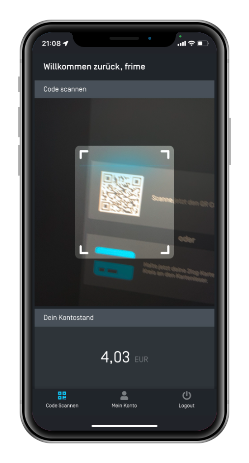
Not everyone likes to carry another smart card. The 2log app for community members provides an alternative to the RFID card. Once the app is linked to your 2log account, just scan the RFID code displayed to authenticate yourself. In addition, the app allows you to keep track of your account balance and transactions.
Where can I get the app?
The Community App is available for Android and soon also for iOS in the AppStore. You will find all further information at https://2log.io/users/
Where can the app be used?
Currently, the app only works with the virtual tally sheet. However, we are already working on an alternative 2log Dot version with a small OLED display. The goal is to make all 2log services compatible with the app as well.
Privacy Policy
The 2log app for community members as such does not store any personal data. However, every action performed with the app (e.g. payment or login processes) could be logged on the server side. Since each operator of a 2log instance is responsible for the collection, storage and processing of data, no generally valid statement can be made here about the storage and processing of data.
Finally, it depends on the infrastructure of the instance operator which data is stored and for which purposes it is processed. Please contact the operator of the instance for further information.
7 - Selling Products
Here you will learn how you can sell products with 2log.io
Members can also use their 2log account to pay for products. For this purpose, there is the so-called “tally sheet”, which implements a simple payment system in the form of a self-service terminal.
Whether drinks, snacks or materials. It is up to you which products you offer. With the simple product management you keep the prices always up to date and have an exact overview of what was sold in which period.
7.1 - Manage Products and Prices
Learn how to add products and manage prices
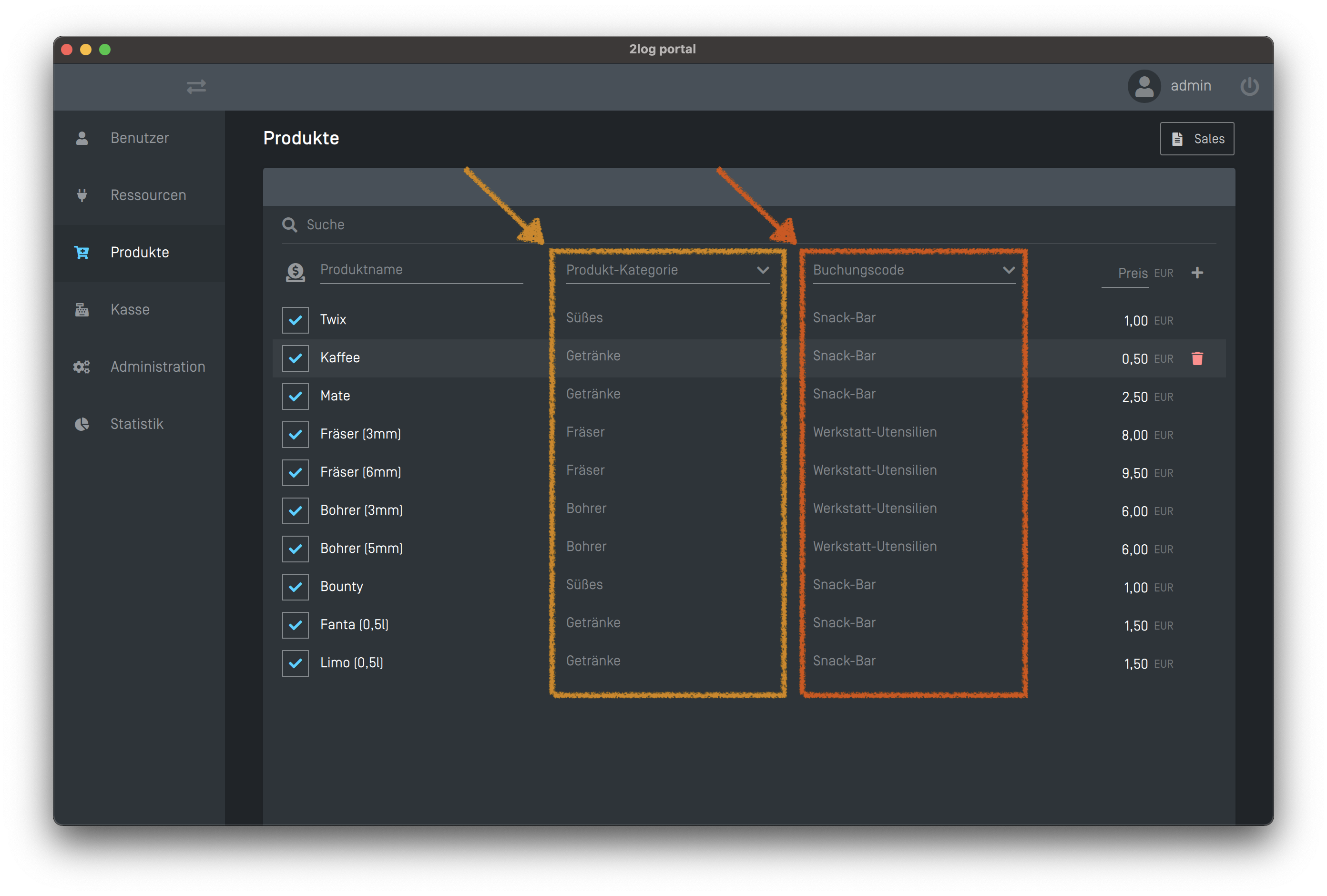
2log offers a simple product management. With it you can add products, group them into categories, manage prices and assign booking codes. Log in to the 2log Admin Portal and click on the “Products” tab.
Attention!
Note that the product names cannot be changed afterwards! This decision was made to prevent errors in the sales statistics. So make sure to name the products correctly and unambiguously.
The mysterious Checkbox
The checkbox activates the corresponding product for the tally list. This can be used to hide products that are temporarily unavailable.
Category
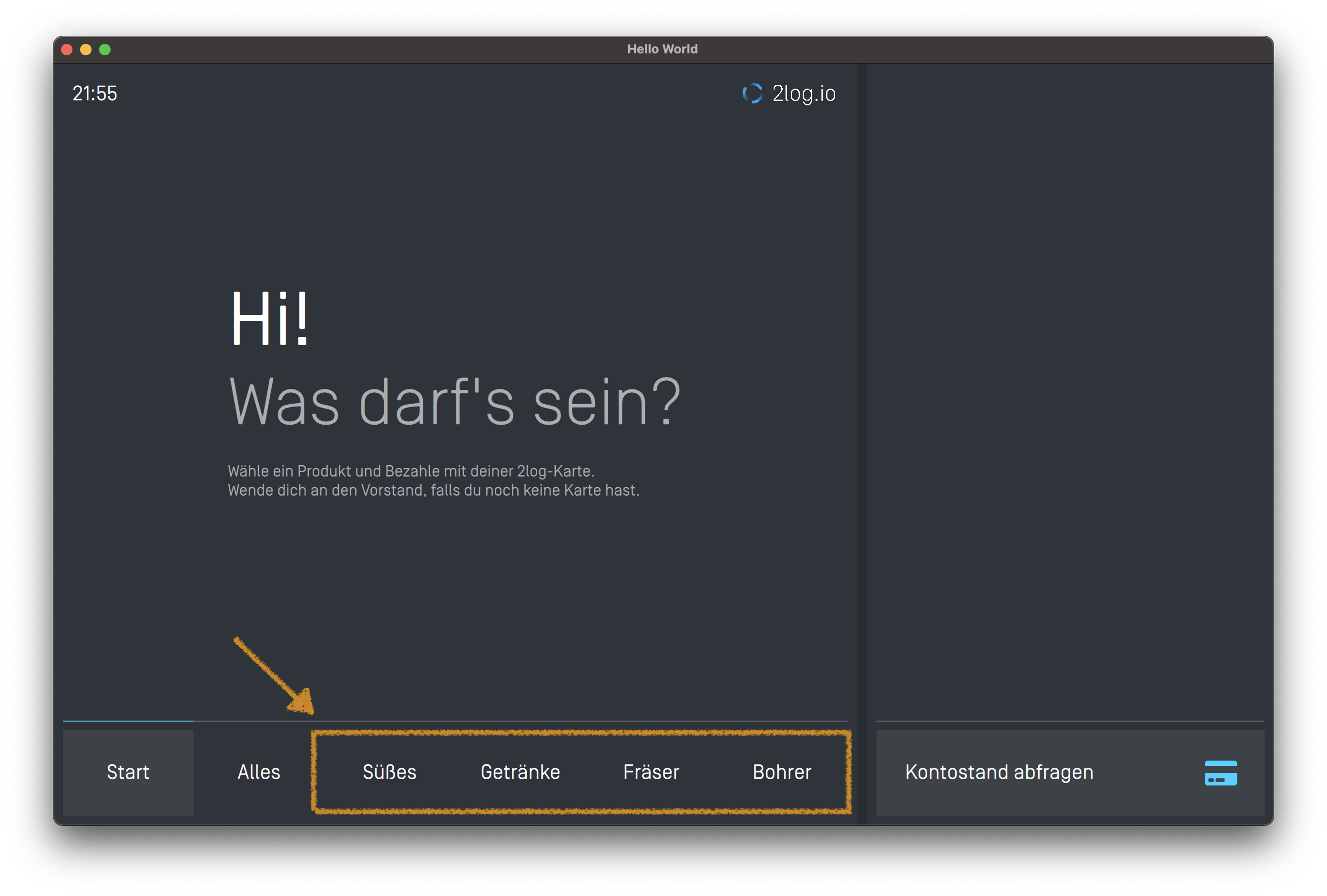
The product category is only a logical grouping to increase the clarity, so that the desired product is found faster. In the tally list, a separate tab is displayed for each category. The category has no influence on the billing.
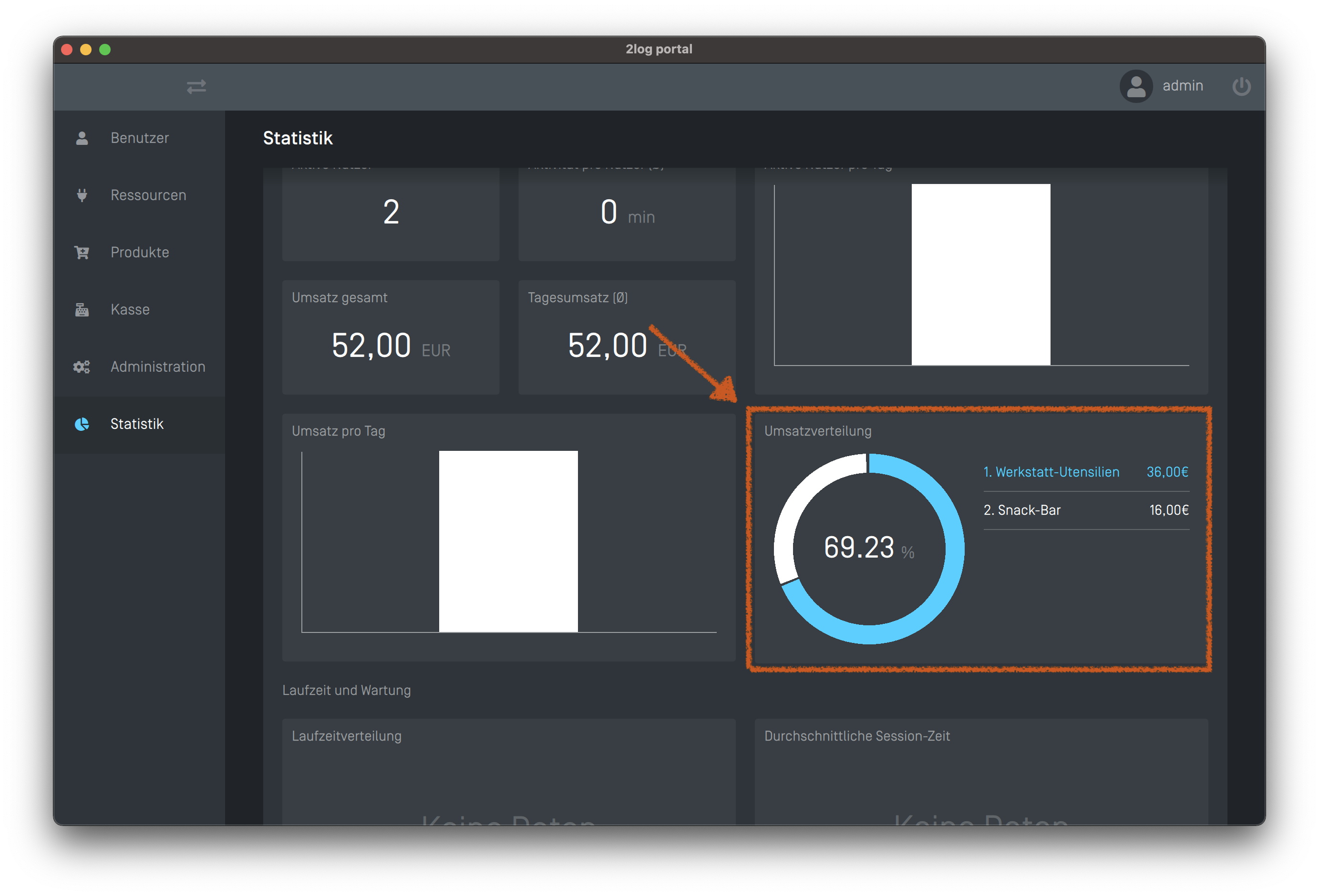
Accounting Code
The booking code is taken into account in the statistics and is used to distribute the revenue to different positions.
7.2 - The 2log.io Tally Sheet
Here you will learn how to set up the 2log tally sheet
The 2log tally sheet is a graphical interface for billing all kinds of products in the style of a self service vending machine. The products offered can be managed centrally via the 2log.io user interface. The products can be paid either with the 2log card or the 2log App by scanning a QR code.
Prepare the Device
The 2log tally sheet runs on all major platforms, if you compile it yourself. Especially single board computers like the Raspberry Pi are a good choice. The easiest way to set up the 2log tally sheet is on a 7" or 10" Android tablet.
Android
This is by far the easiest way to set up the tally sheet:
Just download the APK from here and install it on your tablet.
RaspberryPi
A Raspberry Pi Zero is perfectly sufficient. In the Gitlab repository there are DXF milling files for a nice case. For compiling the sources for the raspberry pi, you can use the docker based cross toolchains.
Pair the Device
The first time you start the app, you must enter the host address of the 2log server.
Log in to the 2log.io admin interface. Switch to the “Administration” tab and open the “Device Explorer” via the button in the top right corner.
The device should now appear under “new devices”. Click on the “+” and assign an address to the device.
Configuration
The SelfService Terminal can be configured via the DeviceExplorer. Depending on the resolution and screen diagonal, it may make sense to set parameters such as the size of the tiles or the font size. Make sure you have added a few products so you can better judge the appearance.
Visual Appearence
You can access the settings via the Device Explorer in the administration area. Just click on the terminal and change the parameters labelFontSize, maxCellWidth and priceFontSize. After clicking on “Send”, the changes are directly transferred to the device and are immediately visible.
Assign a Dot
In order for users to be able to pay with their RFID card later, you need a 2log Dot. The Dot can be assigned to the tally sheet via the 2log admin interface.